Tensile Test
Practical Course Materials Science
Practical Course Materials Science
You may use the items as chapter navigation.
More informations behind the symbol
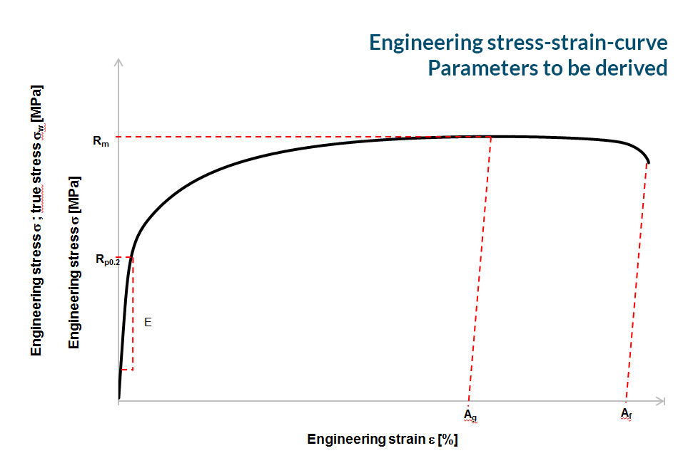
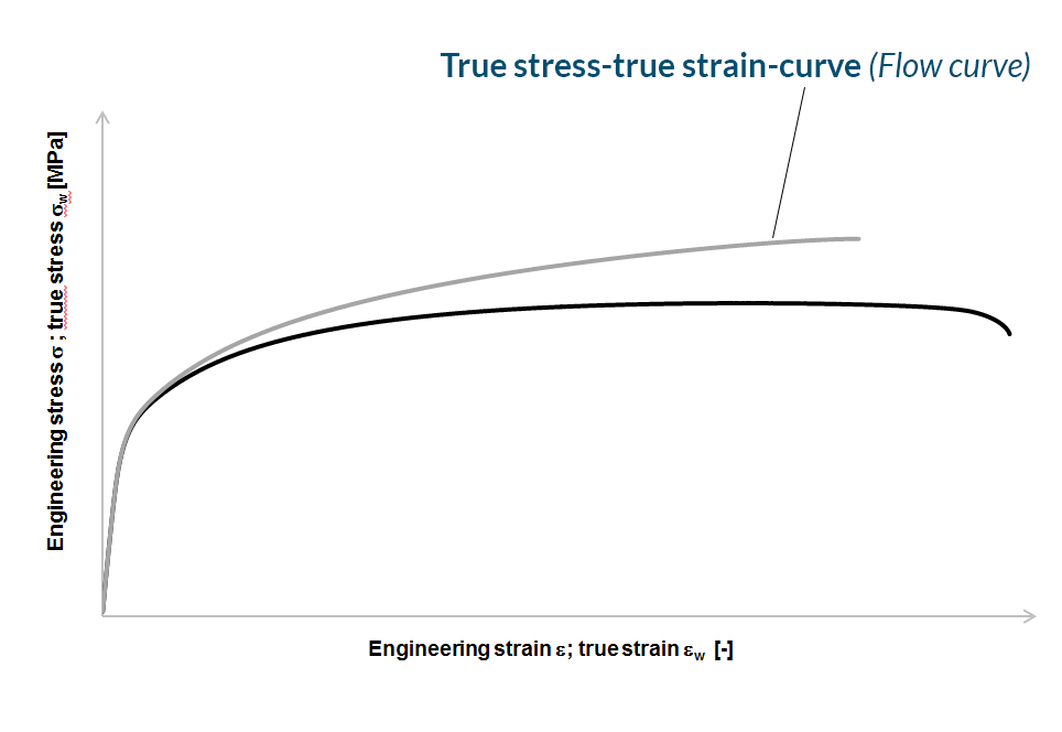
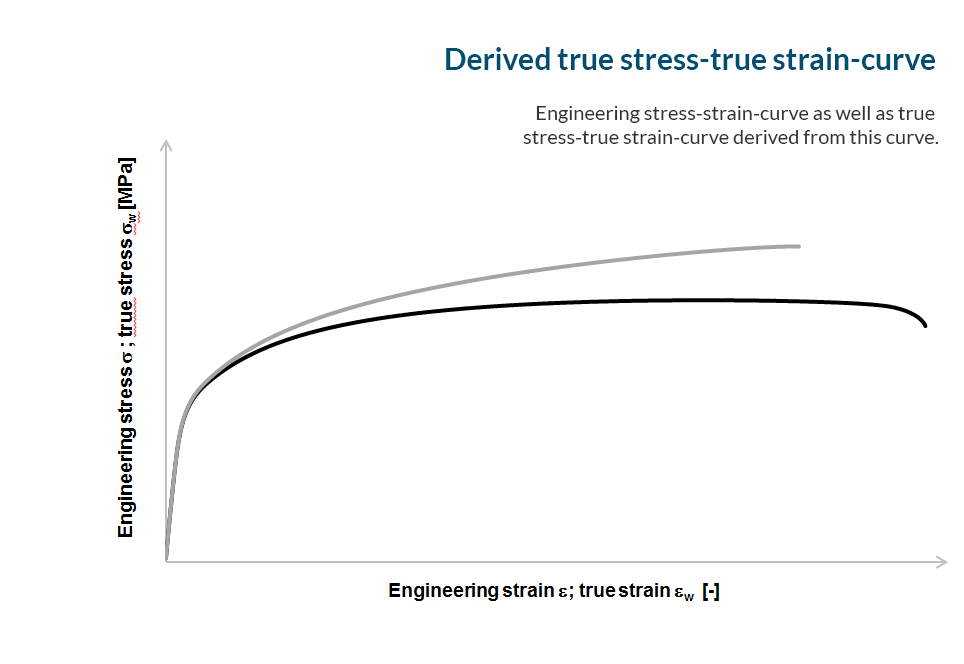
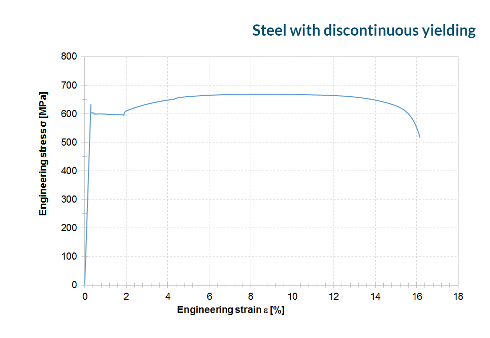
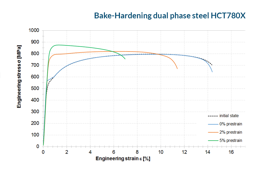
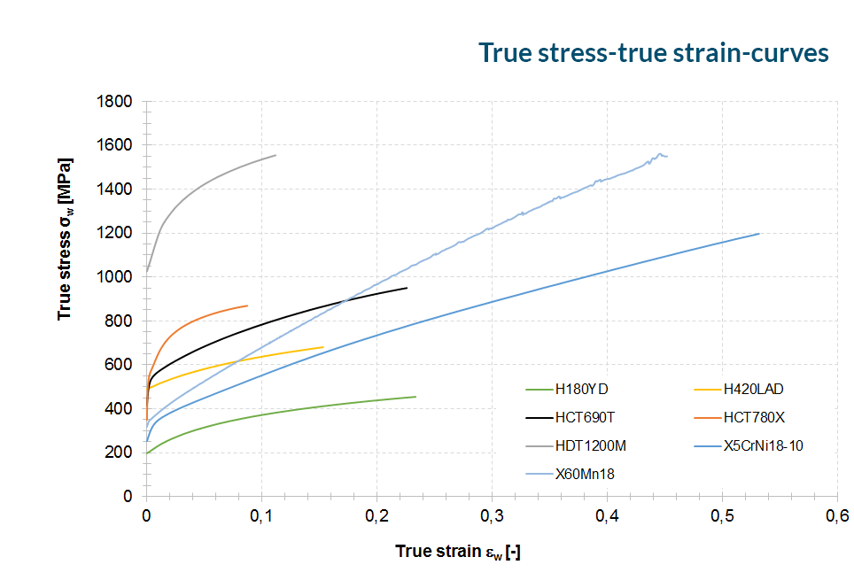
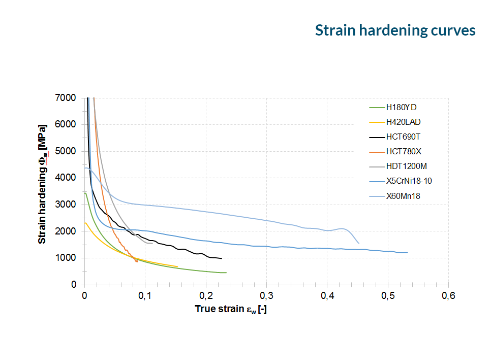
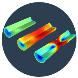
Based on the force and elongation data acquired during the tensile test, engineering stress-strain-curves along with the technological relevant material parameters as well as true stress-true strain-curves, also adressed as flow curve (pages Evaluation), should be calculated.
Curve charts
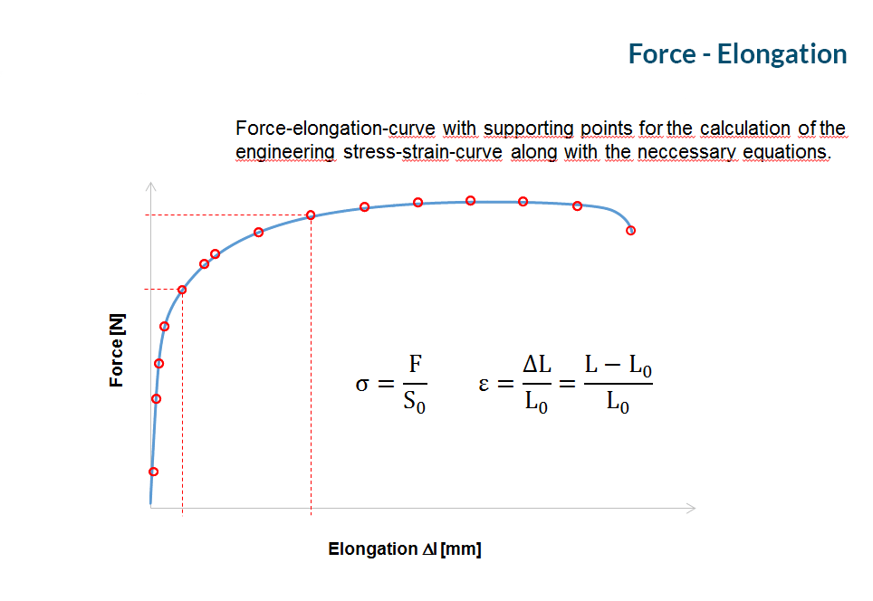
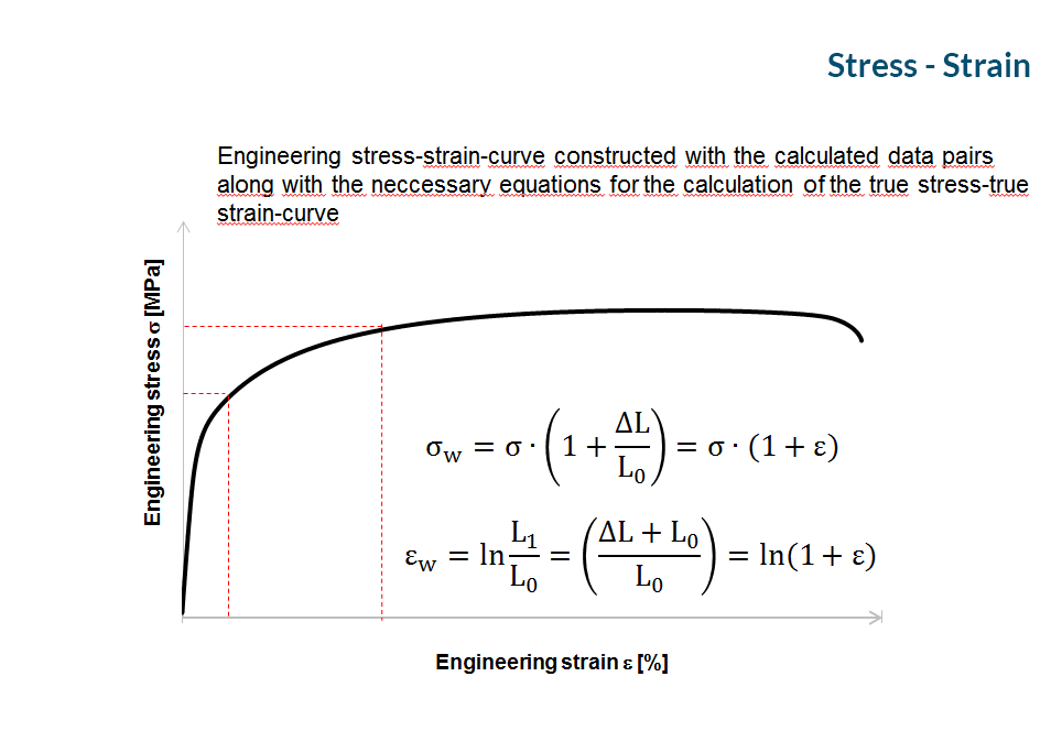
After plotting the recorded force-elongation-curves it is now possible to select appropiate supporting points for the calculation of the engineering stress-strain-curves.

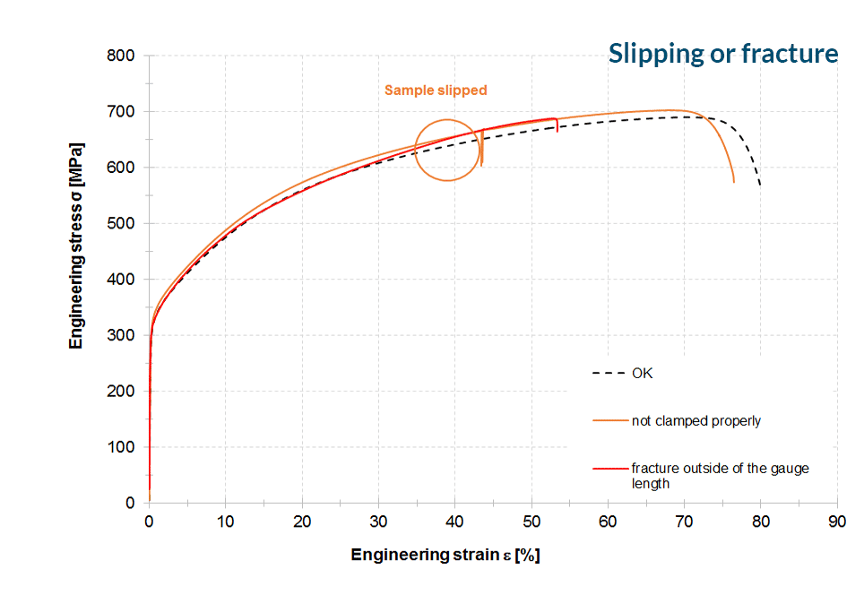
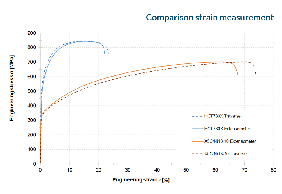
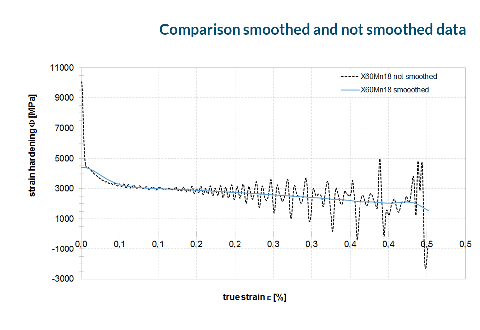
Further examples you will find here:
To prevent measurement errors and injuries you should debur the sample thoroughly. Additionally you avoid damaging the rubber bands holding the steel pins in place.
Caution Make sure you do not grind the edges round!
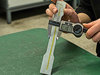
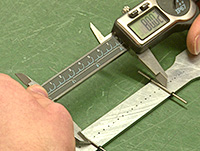
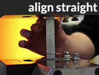
Caution Before measuring the caliper has to be calibrated!
Take multiple measurements and average them.
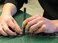
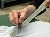
A) First draw the dot matrix with the pattern.
B) Mark the gauge length with the steel pins and the rubber band.
C) Control the required gauge length (80 mm)
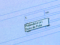
A) Type in the measured and averaged sample dimensions
B) Initial/start load = 0
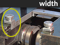
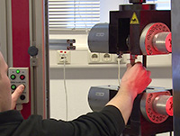
A) Define the sample position with adjusting screws.
B) Press the sample straight in the tensile test machine.
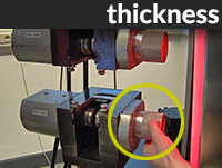
C) Clamp the sample hydraulic or by tightening the screws.
D) Control the sample position in the visual measuring field (left monitor).
E) Adjust if necessary.

A) Setting the strain rate (~ 0.002 s -1) ?
B) Start the test (Button "Start")
A) Untighten the hydraulic cylinders or srews and remove the 2 halves.
B) Tape the halves together and label them.